Quick Overview
VMware NSX-V allows micro-segmentation of your applications, and greatly increases the available VLANS via Logical switching well beyond the standard 4000. With VXLANs a singular overlay network can be utilized to pass these networks, no longer requiring the physical configurations on cabling and trunking of switch ports.
The real issue/difficulty with NSX-V is the lack of multi-tenancy and complexity to configure. The goal of the Morpheus integration was to enhance the user experience configuring common entities within NSX. Essentially, this gives a Cloud Management Platform (CMP) the ability to scope actions and objects to specific sets of users and tenants in a simple and quick fashion while filling the void left originally by VMware.
Lastly, it’s important to note that NSX-V is slated to replaced by NSX-T at some point, though support from VMware continues to extend the EOL.
Goal
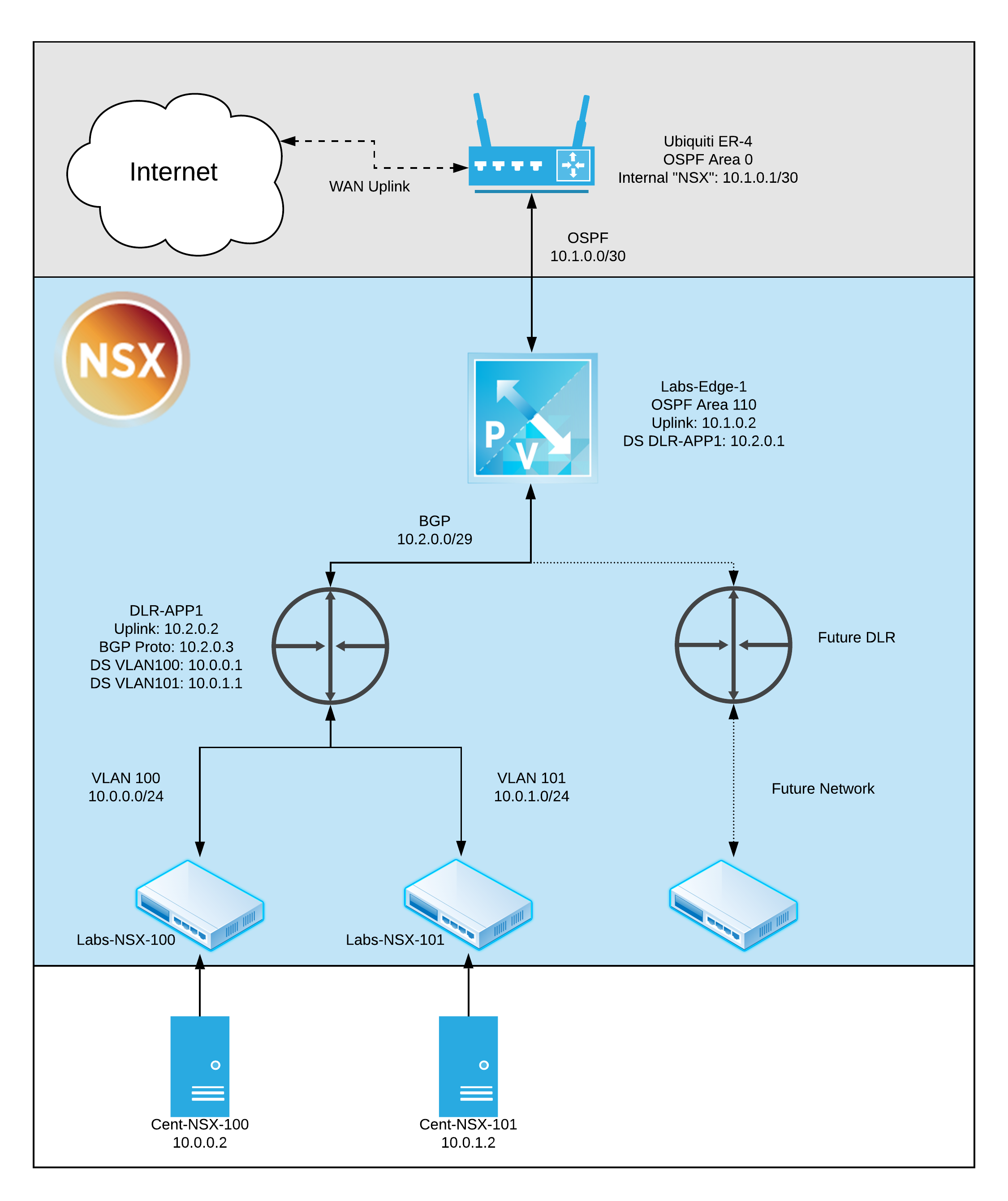
The goal of this project is to enhance my Morpheus environment with a NSX-V integration. I wanted to connect end-to-end with from my virtual machines and containers to my Ubiquiti EdgeRouter 4 (ER-4). The final result will be full external networking, shared/broadcast routing information via BGP and OSPF, and a [nearly] infinite amount of lab VLANs. Ideally this will lead to easily creating networking scopes for containerized apps in future posts. For reference, attached is the goal architecture after deployment.
Note: There are plenty of guides available for initial install and configuration of NSX-V. Essentially, download the bits and deploy the ova, then be sure to stand up a NSX-V controller. After that you are ready to integrate with Morpheus!
Integration and Networks
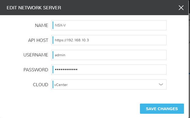
To start off the path of NSX, we must configure the integration within Morpheus. Navigate to Infrastructure > Network > Integrations. Click on Add, and choose NSX-V. Point the integration at the NSX-V controller. At this time, I can map which Morpheus cloud I would like this integration to sync with. Since I only have a singular vCenter, the cloud name in my Morpheus is ‘vCenter’.
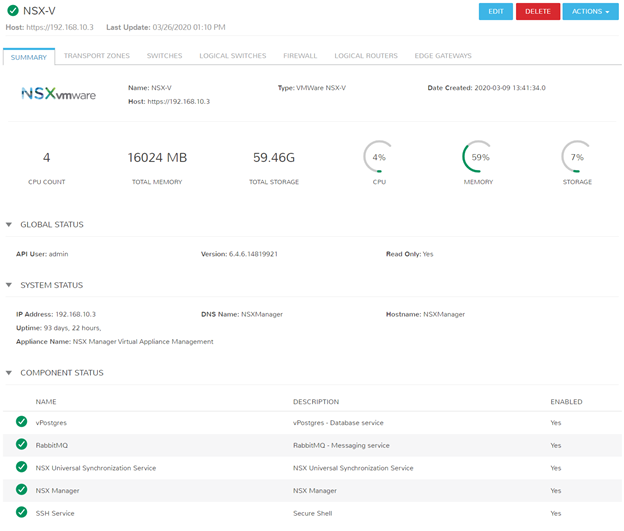
Once the integration is added, click the name defined (In this case I called mine NSX-V), and you’re presented with a summary of the environment including any pertinent services with the controller.
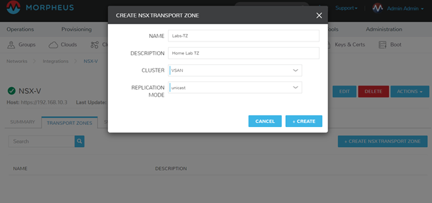
Now that everything is hooked in, I need to create an initial Transport Zone (TZ). Transport Zones define the scope of Logical Switching and Routing. It’s possible to have multiple Transport Zones, perhaps to represent different teams, Morpheus Groups, Morpheus Tenants, or a slew of other reasons.
To create a Transport Zone, navigate to your NSX-V Integration, select the Transport Zones subtab, and create a new TZ.
Note: Transport Zones are maintained on the direct integration pages because it is a higher level action that typical users/tenants will not have to configure.
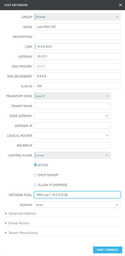
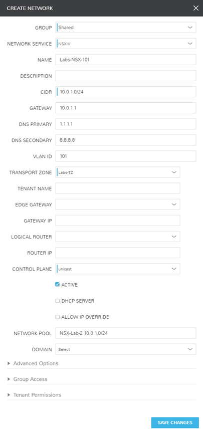
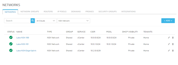
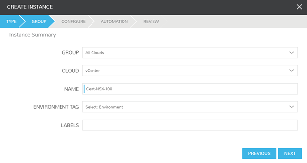
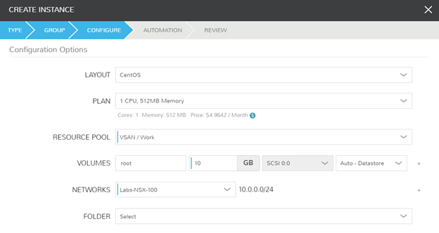
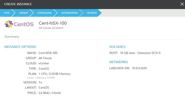
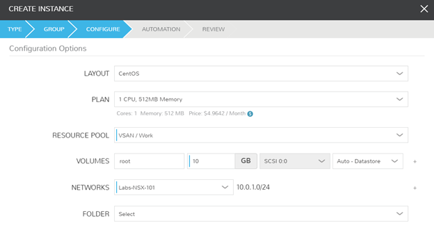
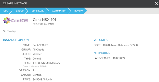
Next, I must define the NSX networks that I want my VMs and containers to consume. In NSX, these are called Logical Switches, and are essentially portgroups presented on dvswitches. In this walkthrough, I’ll create 3 networks:
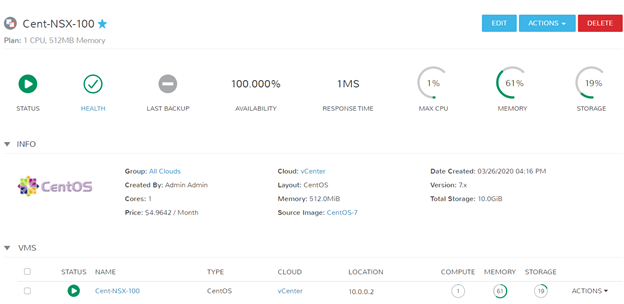
- Labs-NSX-100
- NSX VLAN 100
- 10.0.0.0/24
- Usage: VM/Conatiners
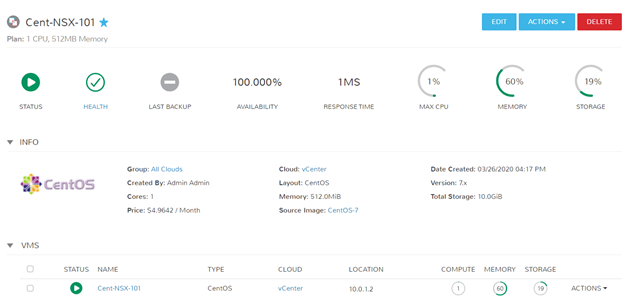
- Labs-NSX-101
- NSX VLAN 101
- 10.0.1.0/24
- Usage: VM/Containers
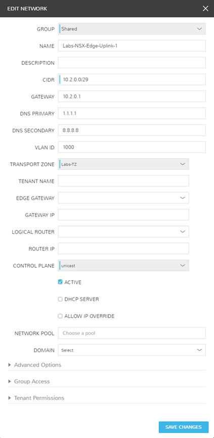
- Labs-NSX-Edge-Uplink-1
- NSX VLAN 1000
- 10.2.0.0/29
- Usage: DLR to Edge Uplink
Notice, I have the ability to link these Logical Switches to IPAM pools. I performed some pre-work to create these VLANs in phpIPAM and used the native Morpheus integration to enhance my use case. Additionally, there are more [optional] questions asked on the Morpheus form than a typical NSX-V Logical Switch. These can create all of the additional mappings via a single form, rather than the multiple locations NSX-V typically requires.
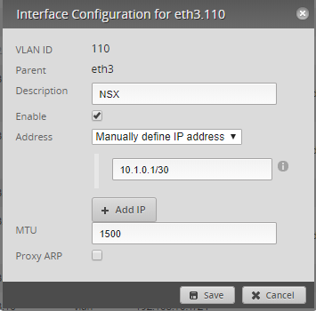
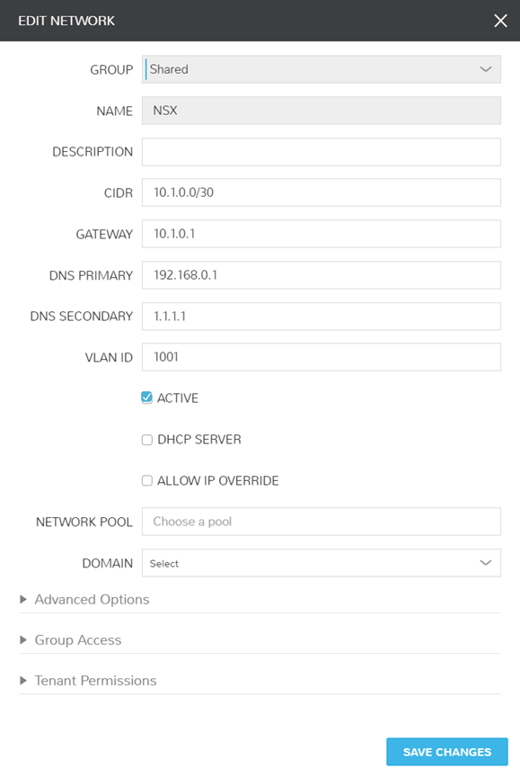
I have created a singular physical network in my environment solely for my VXLAN to Physical network connection. Below are the screenshots of how I have this configured in both my EdgeRouter (Ubiquiti ER-4) and Morpheus. Morpheus automatically synced in the dvswitch portgroup, so all I had to do was modify the network information to provide the additional details.
Routers, Routers, Routers
I’m finally ready to build the routers. First, I’ll build a Distributed Logical Router (DLR). A DLR and Edge Router are similar, however an Edge’s purpose is to connect the internal virtual networks to the external physical layer.
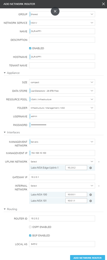
The router ‘DLR-APP1’ will be used to add both VLAN 100 and VLAN 101 as the internal sources, and uplink to ‘Labs-Edge-1’. There are requirements in NSX-V that the DLR’s management network is a tagged portgroup that is not a member of the uplink or internal connections. In this example, I utilized my server VLAN and assigned a static IP.
It is important to note that when selecting the uplink and internal networks, you must click the ‘+’ next to the network to actually attach, as well as define the IP. On the Uplink this is a host IP of 10.2.0.2. On the Internal networks, these represent the gateway to the Logical Switches attached so 10.0.0.1 and 10.0.1.1.
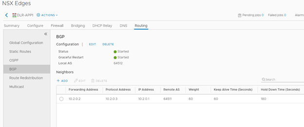
Lastly, note that I’ve checked the box for my DLR to handle BGP Routing. I’ve configured the Local AS 64512 (what the system is identified as). Router-Id’s are typically represented by the external/uplink IP address that will be communicating with the other routers.
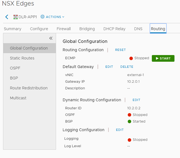
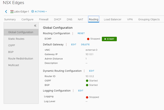
Confirming settings and build inside of NSX. Default Gateway and Routing Configured!
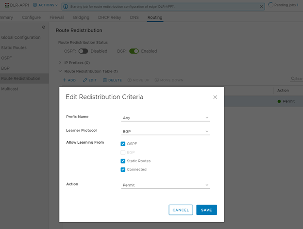
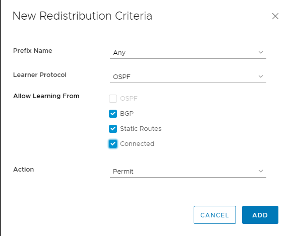
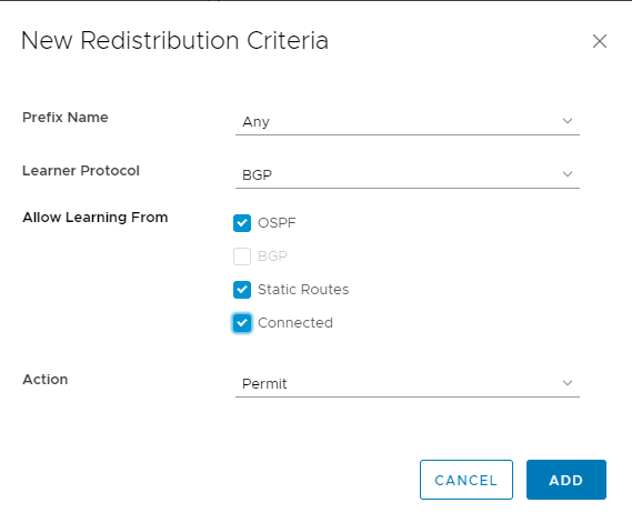
Confirming BGP Redistribution was configured, and I didn’t really care to scope this down from learning routes from OSPF, Static, and Connected.
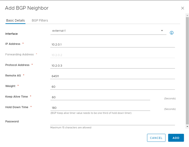
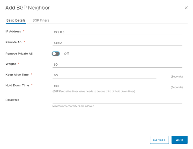
Below is the configuration for a BGP neighbor on a DLR. The DLR has a field ‘Protocol Address’ which the Edge Router wizard does not have. The protocol address instead will be used by the Edge as the neighbor address of the DLR it will be connecting to instead of the DLR’s IP address. Also notice, the ‘Remote AS’ 64511 will be the ‘Local AS’ of my Edge Router.
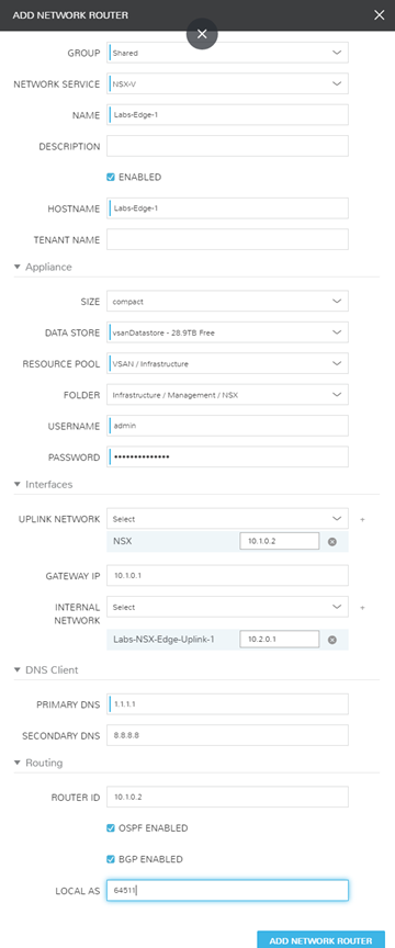
Building the Edge Route for external NSX-V access. My uplink is a /30 network connected to my physical network. Networks can’t be reused on the uplinks so I minimized my IP footprint since I only needed 2 usable. The internal network will be connected to the DLR’s uplink and set as the gateway. Additionally, I’ve configured both BGP and OSPF. OSPF will be sharing routes with my Ubiquiti Router, and BGP will share between my Edge and DLR routers.
Confirming configuration.
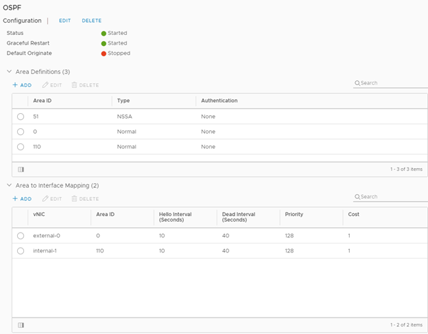
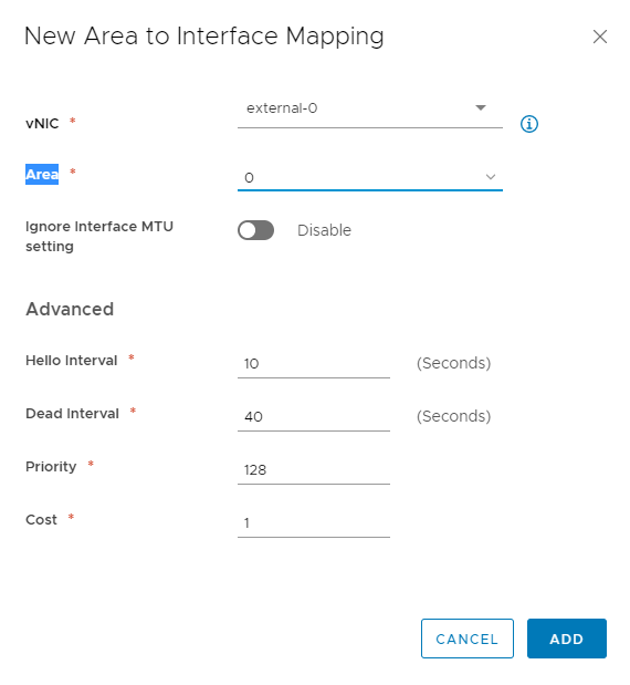
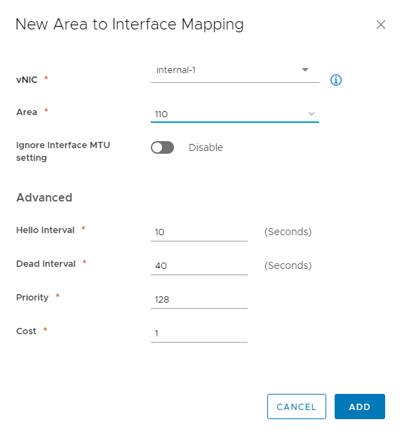
Showing the configured OSPF Areas. Area 0 is my Ubiquiti Router, and Area 110 is my internal NSX networks. Be sure the areas are attached to the correct uplinks for proper route redistribution.
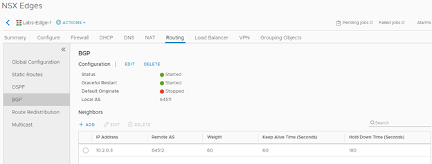
Here I configure the Edge’s DLR neighbor. Notice again, that the IP address is the Protocol Address I defined on previous steps.
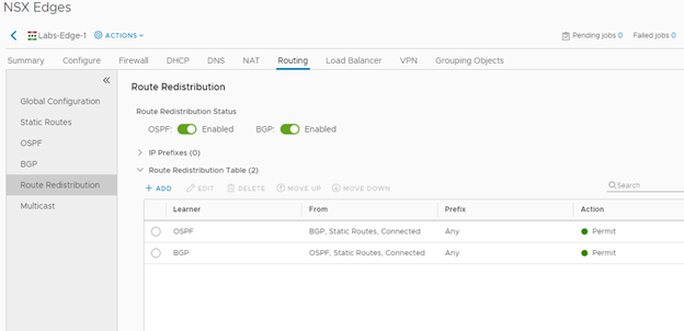
Ensure that both OSPF and BGP Route Redistributions are configured as this Edge will Segway between the Ubiquities OSPF and internal NSX-V BGP.
Configuring Ubiquiti EdgeRouter
To help with folks who have Ubiquiti gear, here are the commands required to do a basic OSPF configuration. I’ve included a screenshot to view what the final configuration should look like in the UI. Those of us who utilize Ubiquiti know how featureless the UI is compared to the CLI.

~$ configure
~$ set protocols ospf area 0
~$ set protocols ospf area 0 area-type normal
~$ set protocols ospf area 0 network 10.1.0.0/30
~$ set protocols ospf default-information originate
~$ set protocols ospf parameters router-id 10.1.0.1
~$ set protocols ospf redistribute connected metric 1
~$ set protocols ospf redistribute static metric 1
~$ commit save
Validate Route Propogation
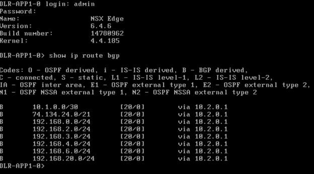
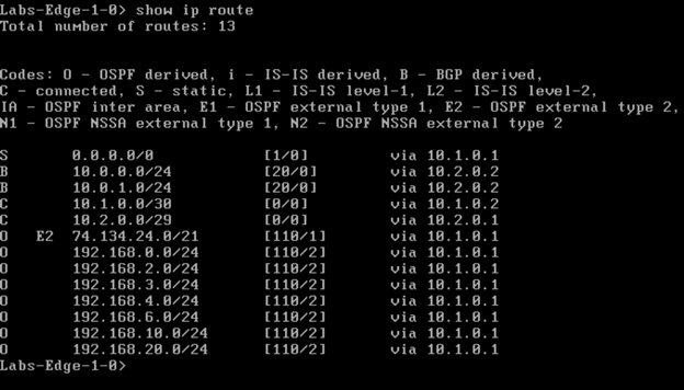
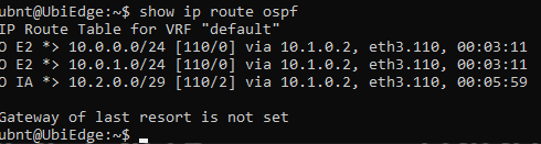
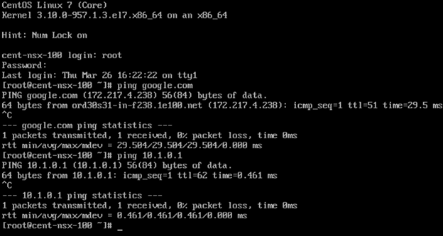
Let’s Test it Out!

Success! I can ping and resolve DNS outside of my network, and I can hit other objects within the NSX environment.
Extra Notes
Now that I have a way to configure new networks via Logical Switches, I can begin micro-segmenting new lab builds. Morpheus has additional controls over firewall management on both the Router level and Distributed Firewall (DFW) level. In my tests above, I had simply created a wide-open bi-directional policy on both of my routers to validate within this test. I can now restrict ports and lock down the environment as needed.